Circuit diagram of not gate using nand Not gate The not gate
Scavenger's Blog: NOT GATE
Transistor resistor transistors nand Designing not gate using transistors Gate circuits circuit integrated does work
Gate ic circuit 74ls04 pinout logic diagram xnor gates working chip circuitdigest nor hex input electronic electrical engineering diagrams circuits
Electronics projects: how to build a not gate circuitDigital logic Scavenger's blog: not gateGates gate circuits digital tutorial output diagram input single has.
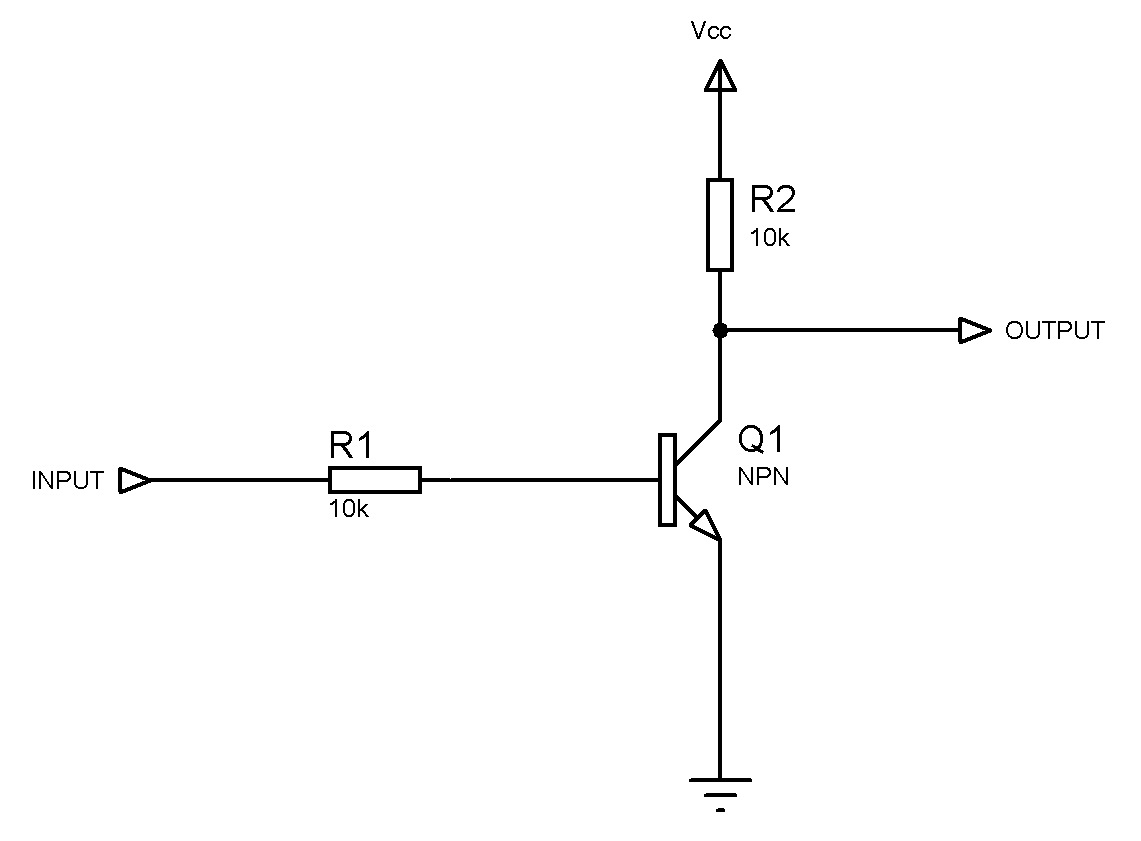
Circuit gate inverter logic electric instrumentationtools digital transistor gates reverse state high circuits switch saturating iv volume lessons ttlGate circuit logic gates diodes schematic input operation analysis transistor steer purpose current these Not gates tutorialNot gate circuit diagram and working explanation.

12+ not gate circuit diagram
Not gate: how does it work? (circuit diagram & working principleRobots reloaded: integrated circuits Simple "not gate" schemeGate circuit transistor logic inverter using.
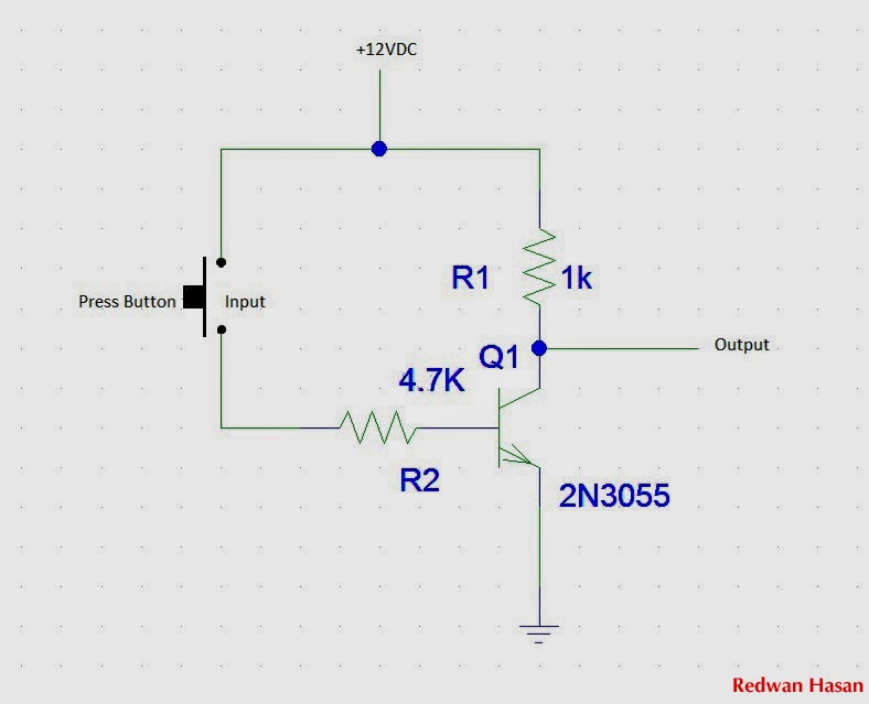
Retro electronics: diy resistor-transistor logic gatesCircuit gate diagram Gate circuit switch switching open logic lamp symbol when will illustrates glow go off figureA simple circuit with a not gate.

Gate circuit using transistor stack flow through schematic electronics exchange circuitlab created digital
Nor gates electronicshubDigital logic How to make a not gate circuitTransistor logic not gate.
Gate transistor npn using circuit gatesExclusive or gate (xor gate) – from reading table Circuitglobe logicGate 7404 circuit ic diagram gates led used vcc input using output part arduino ground timer electronics funny cube animated.

Design of basic logic gates using nor gate
Transistor logic gerbang bjt npn inverter ttl transistors rtl gatter nor saturation logika aufgebaut input dasar jfet74ls04 pinout, features, equivalent, examples & datasheet Not gate circuit diagram and working explanationGate circuit.
74ls04 gate hex diagram gates circuit inverting pinout components101 input transistor forming shown choose board which ic datasheetTransistor gate inverter logic gates circuit diagram gif ttl petervis used What is not gate inverter, not logic gate inverter circuit using transistorGate using circuit transistors transistor diagram circuitdigest designing proteus.

Not gate circuit
What is not gate inverter not logic gate inverter circuit usingDiode equivalent circuit of and gate Rgb led circuitNot gate circuit.
Transistor inverter logic complementary transitorsCircuit led gate electronics eevblog forum power Gate exclusive xor nand inverterNot gate circuits.

Gate circuit diagram electrical4u transistor principle working
What is not gate inverter, not logic gate inverter circuit using transistorWhat is a not gate? Gate circuit diagram input power through circuitdiagram button explanation connected thenGate circuit dummies.
Gate inverter logic circuit transistor uncategorizedPractical inverter circuit (not gate) Not gateCircuit gate diagram simple.

Digital logic
Animated 555 circuit to make patterns in 3*3*3 led cube (part 1 .
.

digital logic - Why does an inverter circuit (NOT gate) need both a
Scavenger's Blog: NOT GATE

digital logic - In a NOT gate circuit, does charge not flow through

NOT Gate - Circuits - Circuit Diagram

Not gate circuits